A wiring diagram is a streamlined standard pictorial representation of an electrical circuit. Exactly what is a wiring diagram.
 Technology
 A wiring diagram is a simplified conventional photographic depiction of an electric circuit.

Flasher can wiring diagram. A wiring diagram is a basic graph of the physical links and also physical design of an electric system or circuit. Today we are delighted to announce that we have found a very interesting content to be pointed out that is flasher wiring diagram 12vmost people attempting to find specifics of flasher wiring diagram 12v and of course one of them is you is not it. Or it may just hang by its wiring behind the instrument panel.
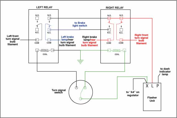
Each part should be placed and linked to other parts in specific way. They will combine the brake wiring and the turn signal wiring so they will work. Turn signal flasher wiring diagram led turn signal flasher wiring diagram motorcycle turn signal flasher wiring diagram turn signal flasher circuit diagram every electric arrangement consists of various unique parts.
The flasher unit may be fixed by a small bracket held by one or two self tapping screws or a push fit in a spring clip or plugged into the fuse box. It shows the components of the circuit as streamlined forms and the power and signal links between the devices. Turn signal problems and diagnosis can get confusingespecially when a system shares wires and connections with the parking warning and braking light systems.
They look like this. It reveals the elements of the circuit as streamlined forms and the power and also signal links between the devices. If not the structure will not work as it should be.
Some have the tail light wire running through them 4 wire into 3 wire and some dont 3 wire into 2 wire. Flasher wiring diagram 12v here you are at our website. If not the structure wont work as it ought to be.
Collection of 3 pin led flasher relay wiring diagram. It reveals just how the electric cables are interconnected and also can likewise reveal where fixtures and components may be attached to the system. 3 prong flasher wiring diagram 3 pin flasher relay wiring diagram 3 pin flasher wiring diagram 3 prong electronic flasher wiring diagram every electric arrangement is composed of various unique components.
A quick and cheap way that works just as good is a tail light wiring converter for trailers. You can get them at places like napa or here. Each part should be set and connected with different parts in specific manner.
Assortment of led flasher wiring diagram. Most common problem sources include bulbs wires connectors fuses flasher units and switches. When and also the best ways to use a wiring diagram.
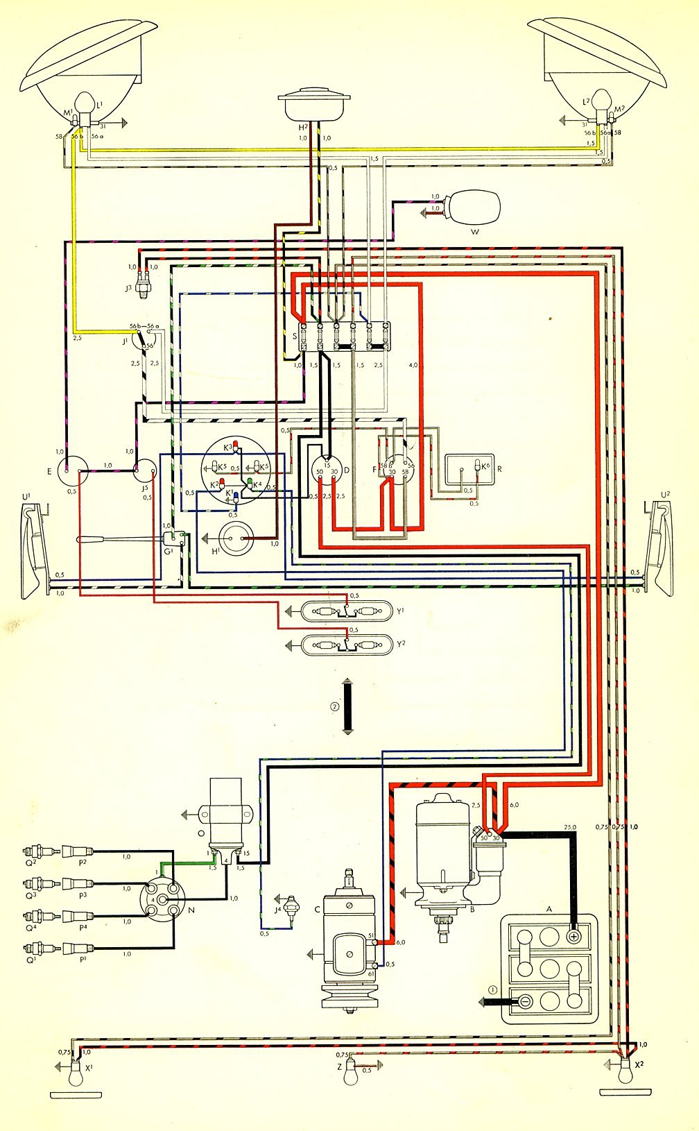 Wiring Diagram For 1960 Vw Beetle Flasher Relay Vw Bug Turn
  3 Pin Flasher Relay Diagram Wiring Diagram Rows
 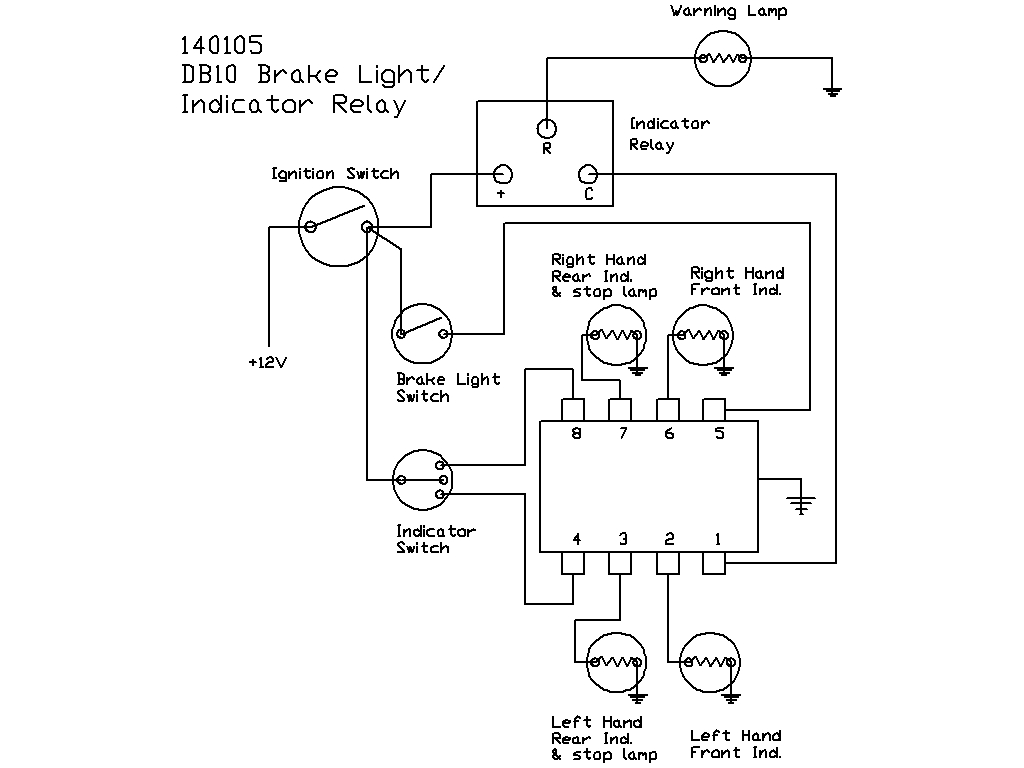 Diagram Citroen 2cv Wiring Diagram Full Version Hd Quality
  3 Wire Turn Signal Diagram Wiring Diagram Priv Speedy Jim S Home Page Aircooled Electrical Hints
  Cherry Switches Wiring Diagram Wiring Diagram Database
  Wiring Diagram For 1960 Vw Beetle Flasher Relay Vw Bug Turn
  Bmw Airhead Motorcycle Miscellaneous Electrical Systems